Introduction
For several years, many Mac-loving geeks have been wishing that Apple would plug a perceived hole in its product line: a moderately priced, expandable mid-tower desktop Mac. The Mac Pro is too expensive, is overkill for many people (more cores than they would use regularly), and lacks PCI slots (many people still have PCI cards they would like to use). The iMac isn’t expandable enough and requires you to buy a new (glossy) display. The Mac Mini is underpowered because of using laptop parts and integrated video.
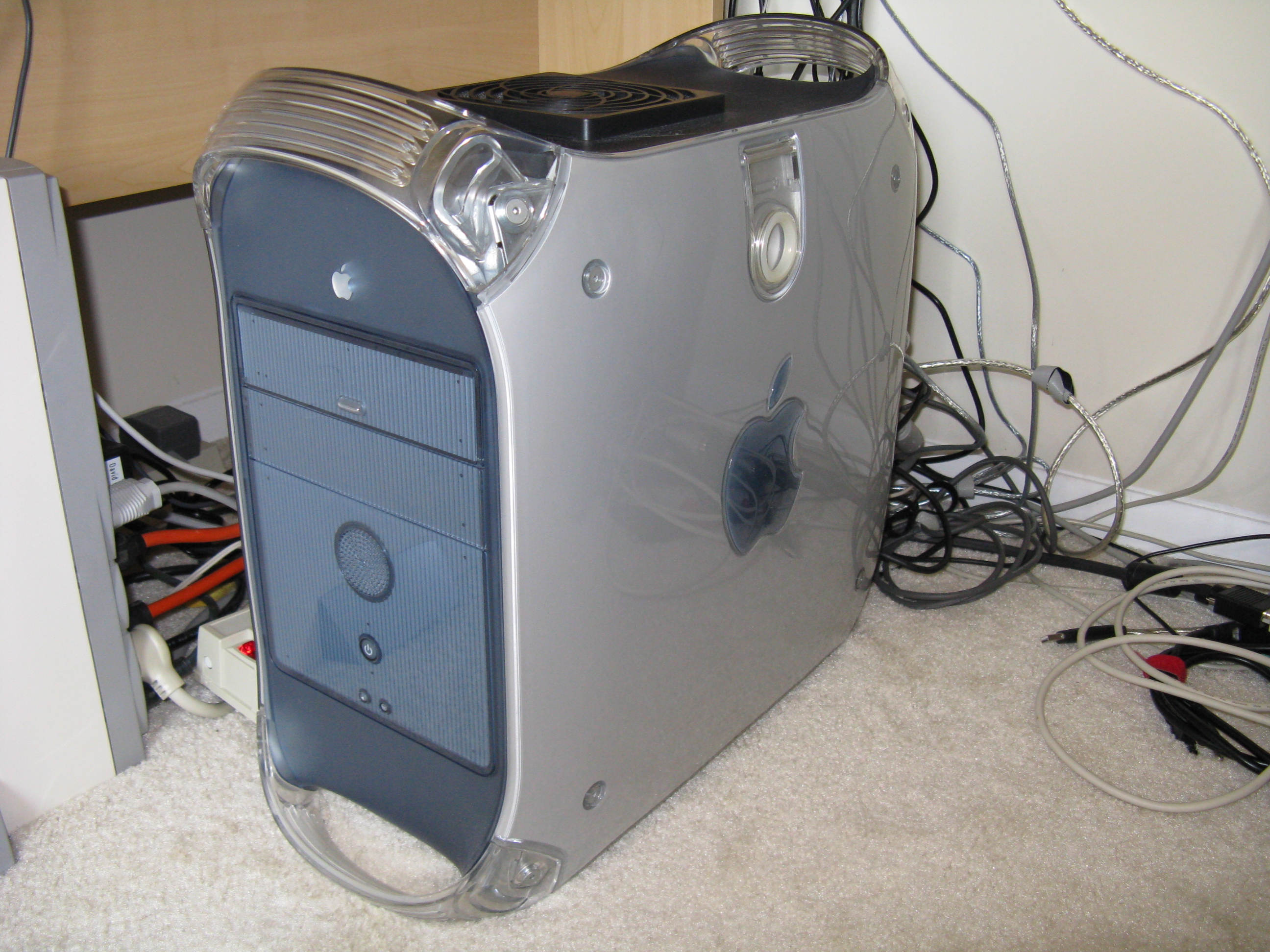
My PowerMac G4 (AGP Graphics model, a.k.a. “Sawtooth”) was becoming frustratingly slow at running modern applications; it didn’t have the CPU power to play many videos encoded with modern codecs like h.264 and Flash VP6. It was upgraded quite a bit, with a 1.4GHz CPU (it had a 400MHz originally), 1GB of PC100 RAM, a 120GB hard drive, and a DVD burner (I mean SuperDrive). I could double the RAM and get dual CPUs (for hundreds of dollars), but the biggest bottleneck seemed to be the 100MHz RAM speed, which compared to G4 Macs with similar CPU speeds but faster RAM, caused jumpy performance, with lots of stalls waiting on the memory. Fixing that bottleneck would require a new motherboard.
I didn’t have over $1,200 to spend on a new Mac, and the Mac Mini is too underpowered to meet my needs, which include video editing. After some research on the web, I concluded that it was possible to convert my PowerMac G4 to an Intel Core2 Duo, producing the missing link in the Mac lineup. Several people have written up how to do it with pictures, though they had somewhat different tools and parts than I did, so I had to figure some parts out myself. Here is how I did the conversion. I’ve always liked the case used in this generation of PowerMacs. I tried to keep the computer looking as stock as I could, to give a “wolf in sheep’s clothing” effect. In some places that wasn’t possible, as I’ll explain.
It can run MacOS X just fine. The MacOS license requires running it on Apple branded hardware, which it clearly still is (just look at it!). OSX just needs a few well-known patches to run on this motherboard.
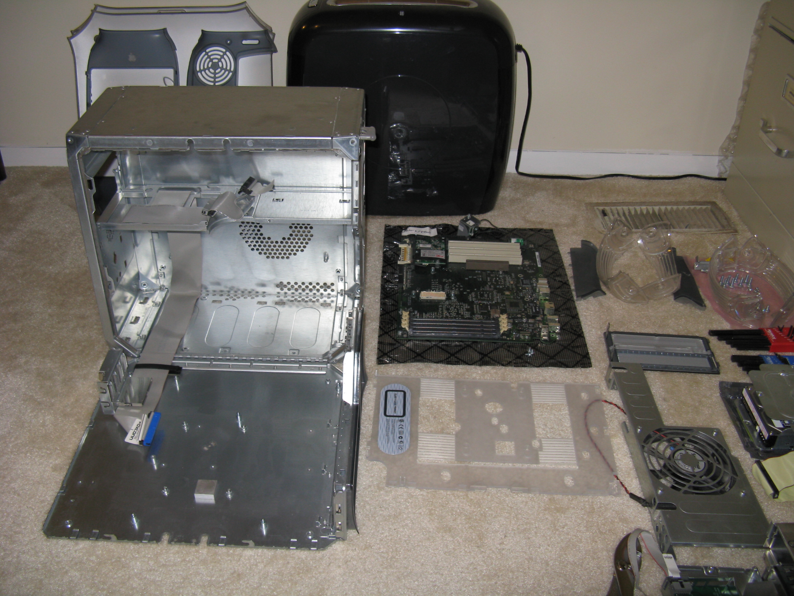
Disassembly
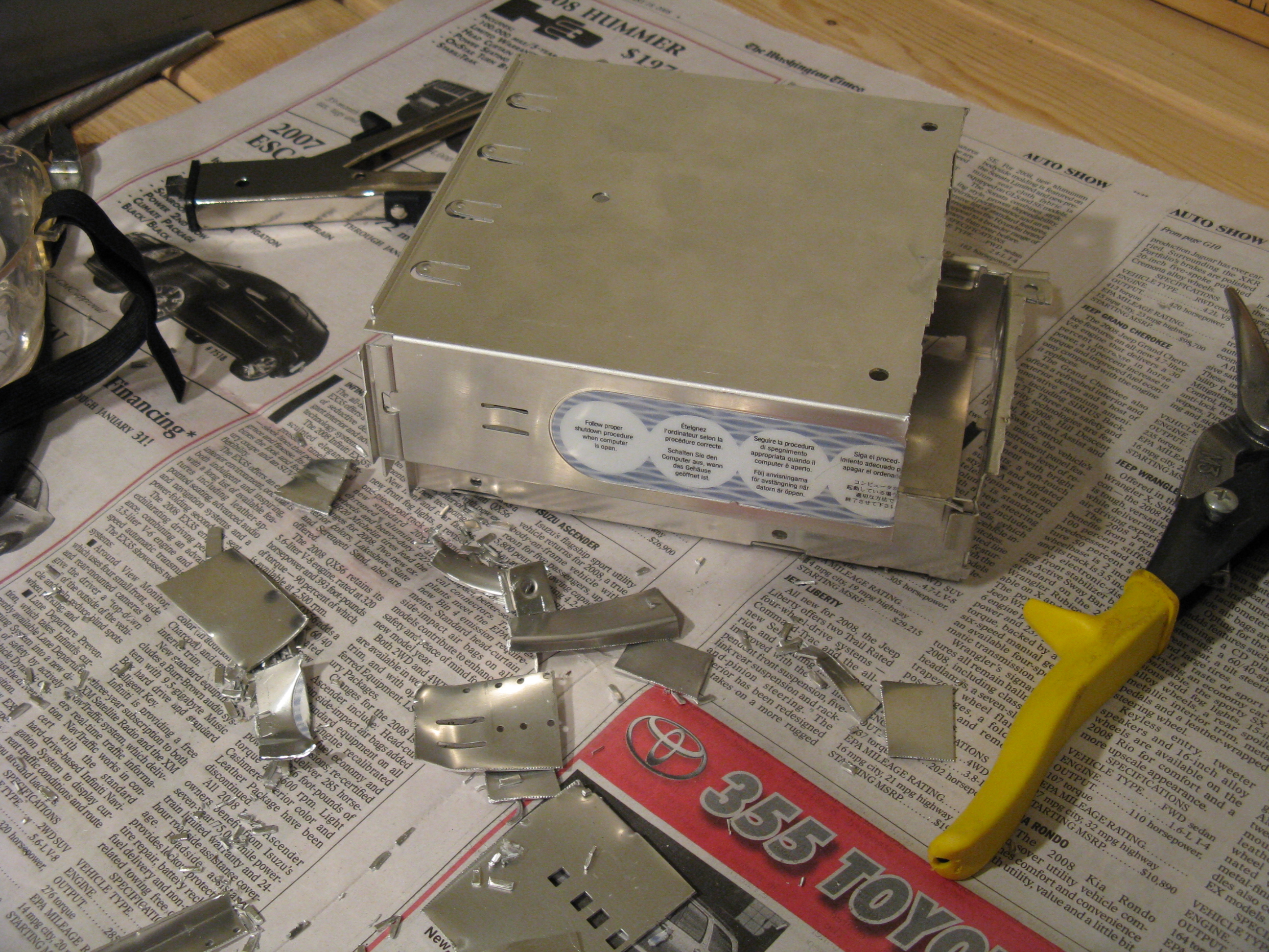
This conversion requires complete disassembly of the computer. There will be a lot of metal and plastic cutting which will cover everything within several feet in little bits of debris.
The optical drive door comes out by bending a couple of plastic tabs. Unscrew and remove the expansion cards, optical drive bay, power supply, motherboard (but not yet the plastic hinge sheet under it), 120mm case intake fan and bracket, and hard drive(s) and carriers. Pry the optical drive data cable off of the double-sided foam tape and scrape the foam off with a putty knife and goo remover.
The four handles and two side panels come off with an Allen wrench. In addition, the center of the Apple logo on the side panels has a couple of pinch tabs on the inside that hold the panel on. I used pliers to pinch them together to release the panels. The handle is held on by a pair of screws. Pop out the speaker and the front panel circuit board by pushing the metal tabs.
The top plastic panel slides off, and the front and rear plastic panels have push tabs. I couldn’t figure out how to remove the plastic panel on the door around the PCI slots, so I left it on. Unscrew and remove the Airport antenna that wraps around the case (unless you want to try using it; I don’t use wireless on my desktop computers).
The motherboard mounts and Airport riser on the door snap off after a few twists with pliers. There is an aluminum block on the door of the AGP Graphics model, which doesn’t come off. It serves as a heat sink for a chip on the bottom of the G4 motherboard. I spray-mounted a piece of an anti-static bag to the top of it to prevent it from shorting out anything on the new motherboard. I let a little of the bag overhang the sides to protect the motherboard from shorting against the block’s side.
Backplate hole
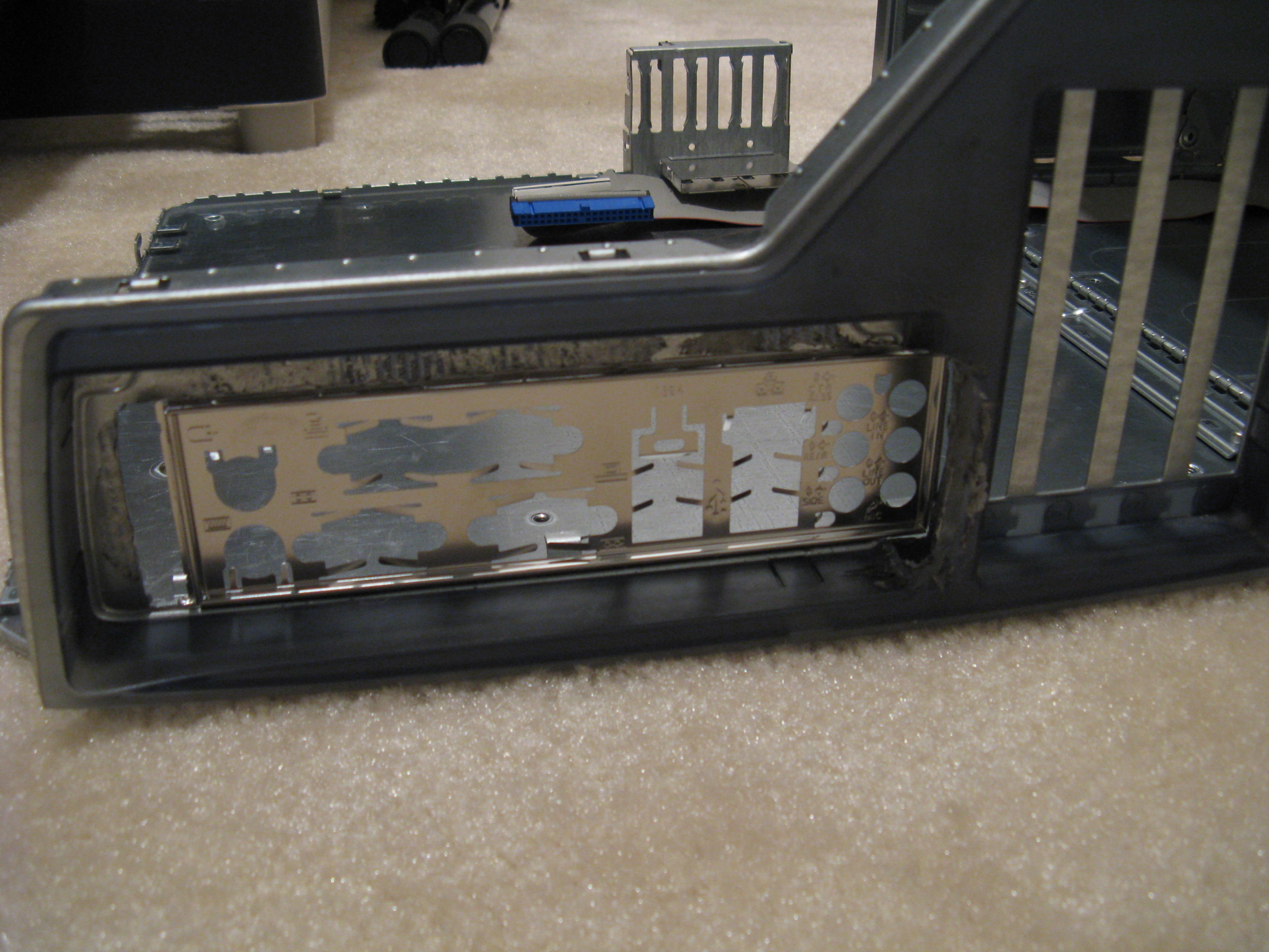
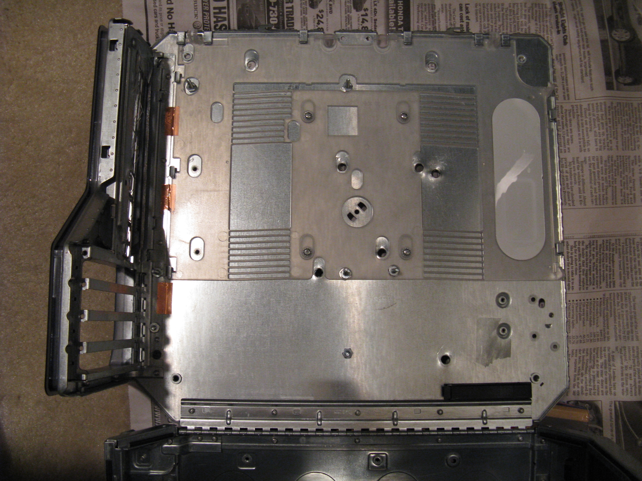
I started by cutting out the back panel so I could determine exactly where the new motherboard would go. This was perhaps the slowest part of the project, as the case metal is thick and I wasn’t sure where the edges of the hole needed to be. I started out using a combination of metal snips, metal nibbler, Dremel cutting wheel, and Dremel polishing brush. Then I switched to a jigsaw with a thick metal cutting blade, which went much faster. Cut with the saw on the outside of the case as much as possible, to avoid damaging the plastic case back.
To fit a standard ATX backplate, you need to cut the G4 cover plate out all the way down to the plastic on the side where the bottom of the motherboard is. On the bottom of the hole (with the case closed and upright), you have to cut into the plastic and about halfway through the bar that separates the motherboard cutout from the video card slot. I couldn’t find a neat way to do that, as the angle is awkward. The best tool seems to be a jigsaw.
This particular PowerMac model required no cutting to fit a standard ATX power supply (although extension cables are needed to reach the motherboard). Later PowerMac G4 revisions might need some plastic cutting.
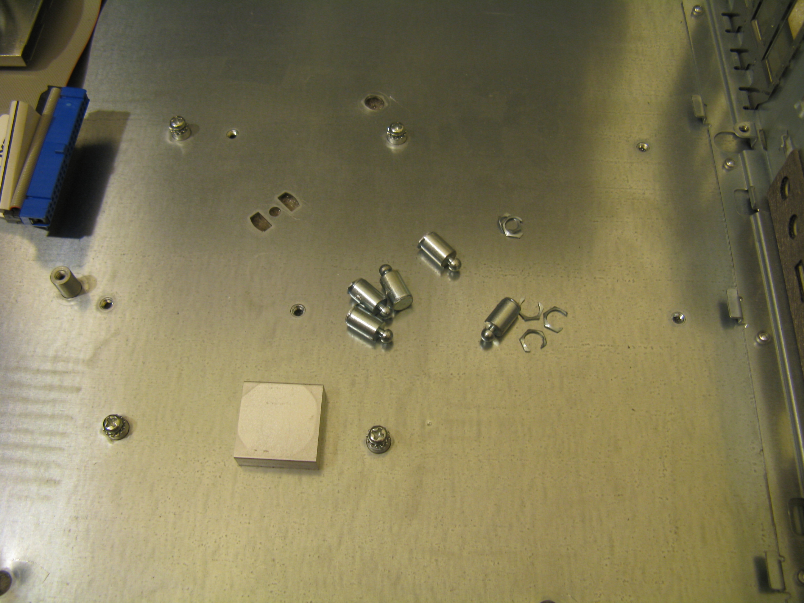
Motherboard mounts
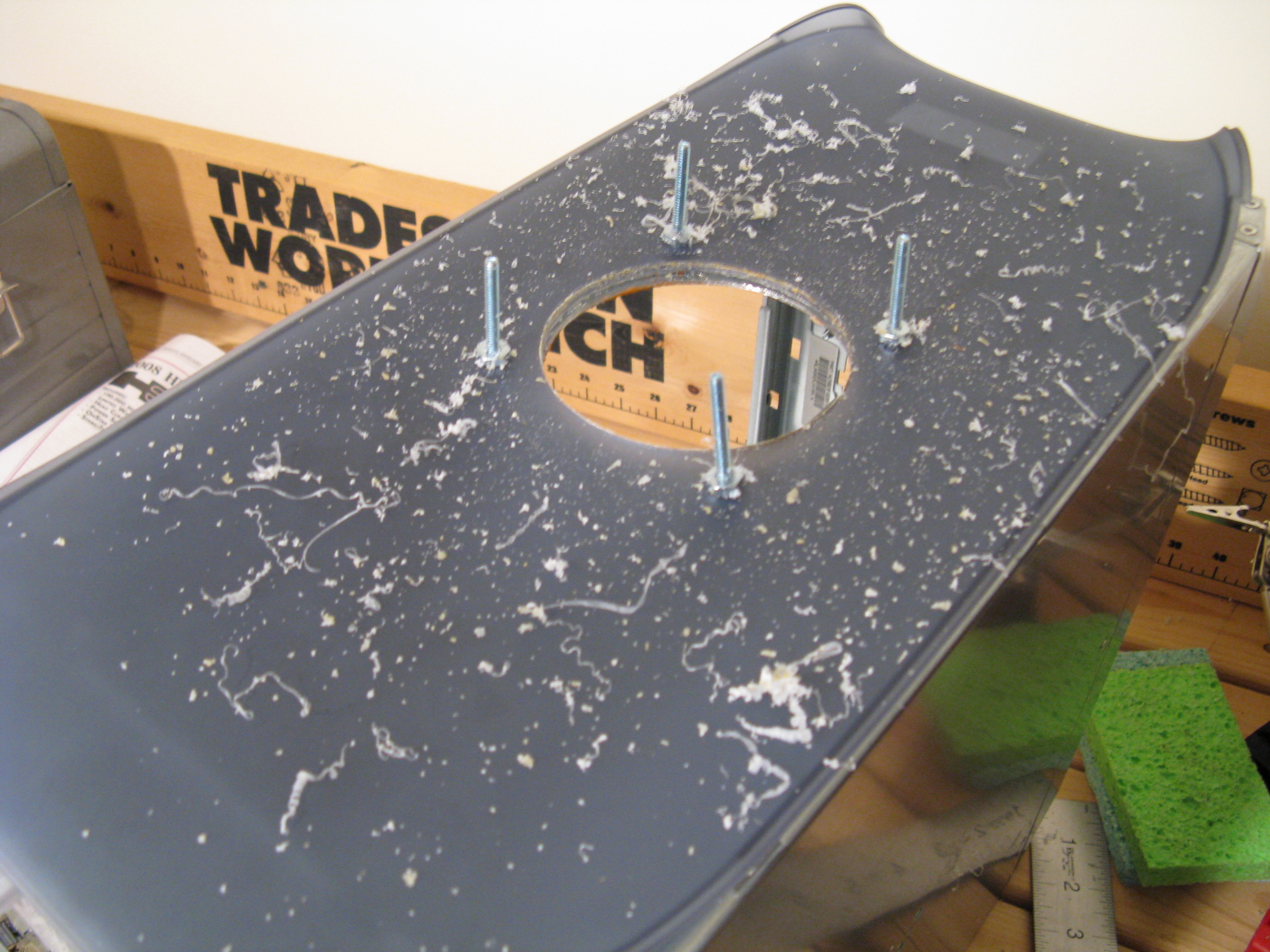
People have used several methods for mounting a new motherboard in a G4. The easiest for me to get was nuts and bolts. The next step is to drill holes for them.
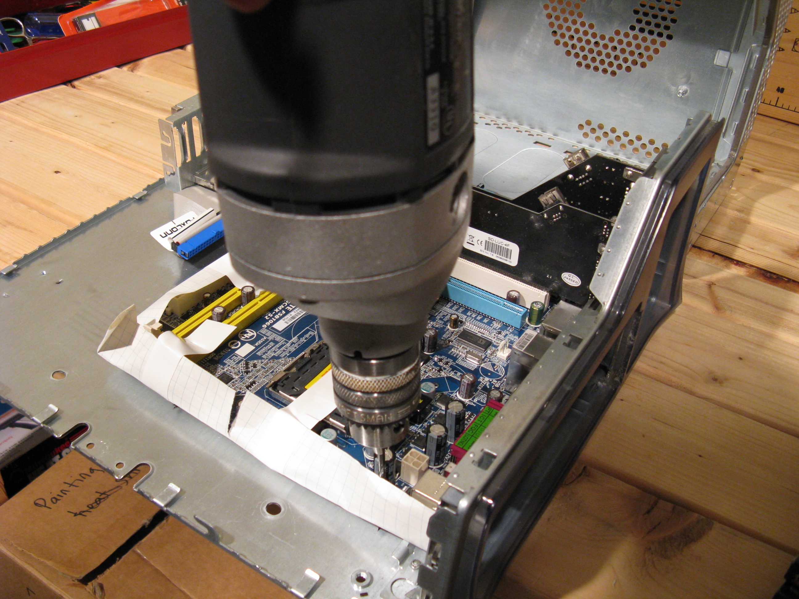
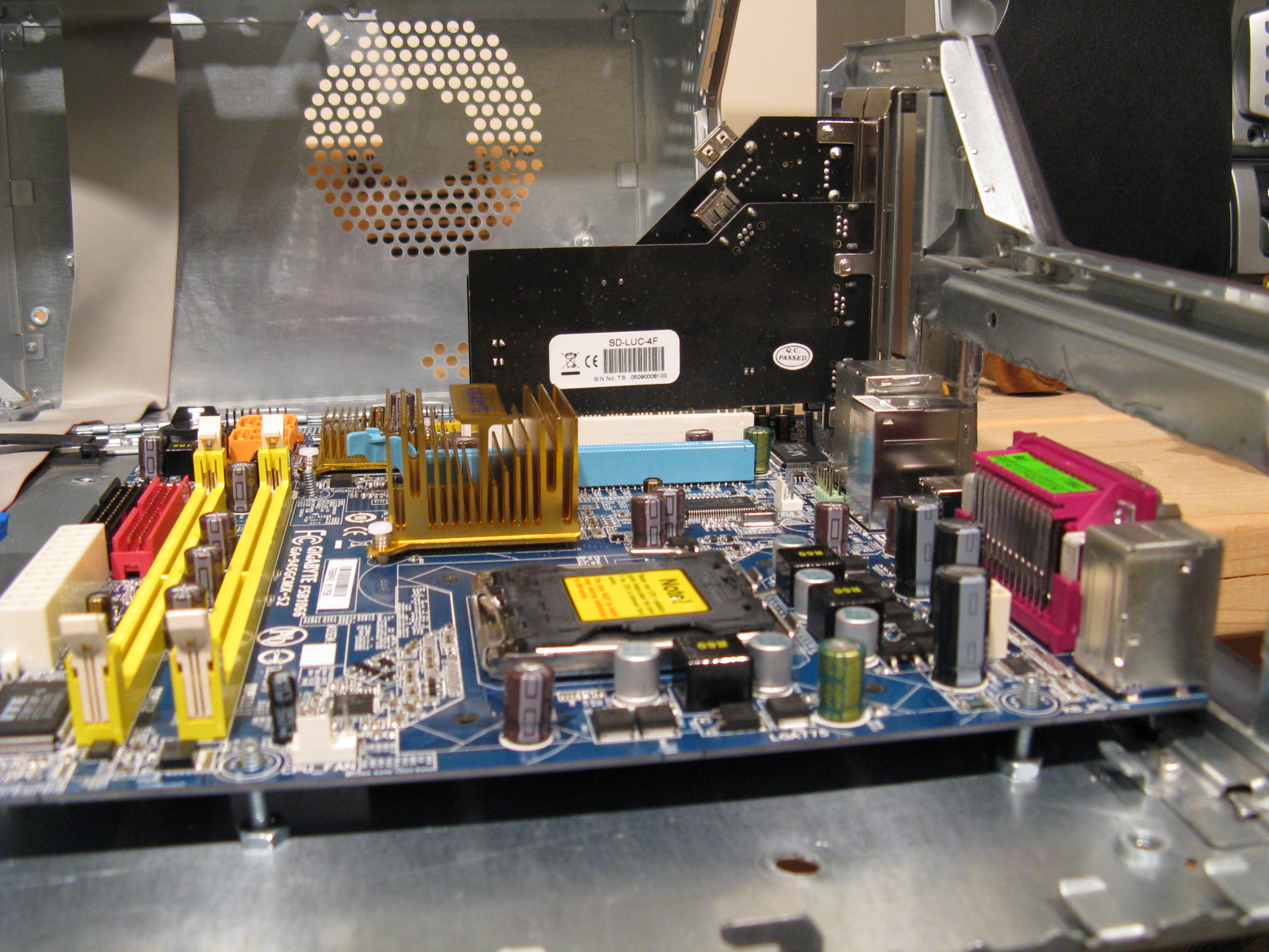
Once you have a big enough hole for the ATX backplate, test-fit the motherboard and screw in at least one expansion card to align it. Mark holes on the case door for new motherboard mounting holes. I had the best success by drilling the holes with the motherboard in place. To be cautious, you can tape paper to the bottom of the motherboard to protect it from debris, or use an old scrap motherboard for the drilling phase.
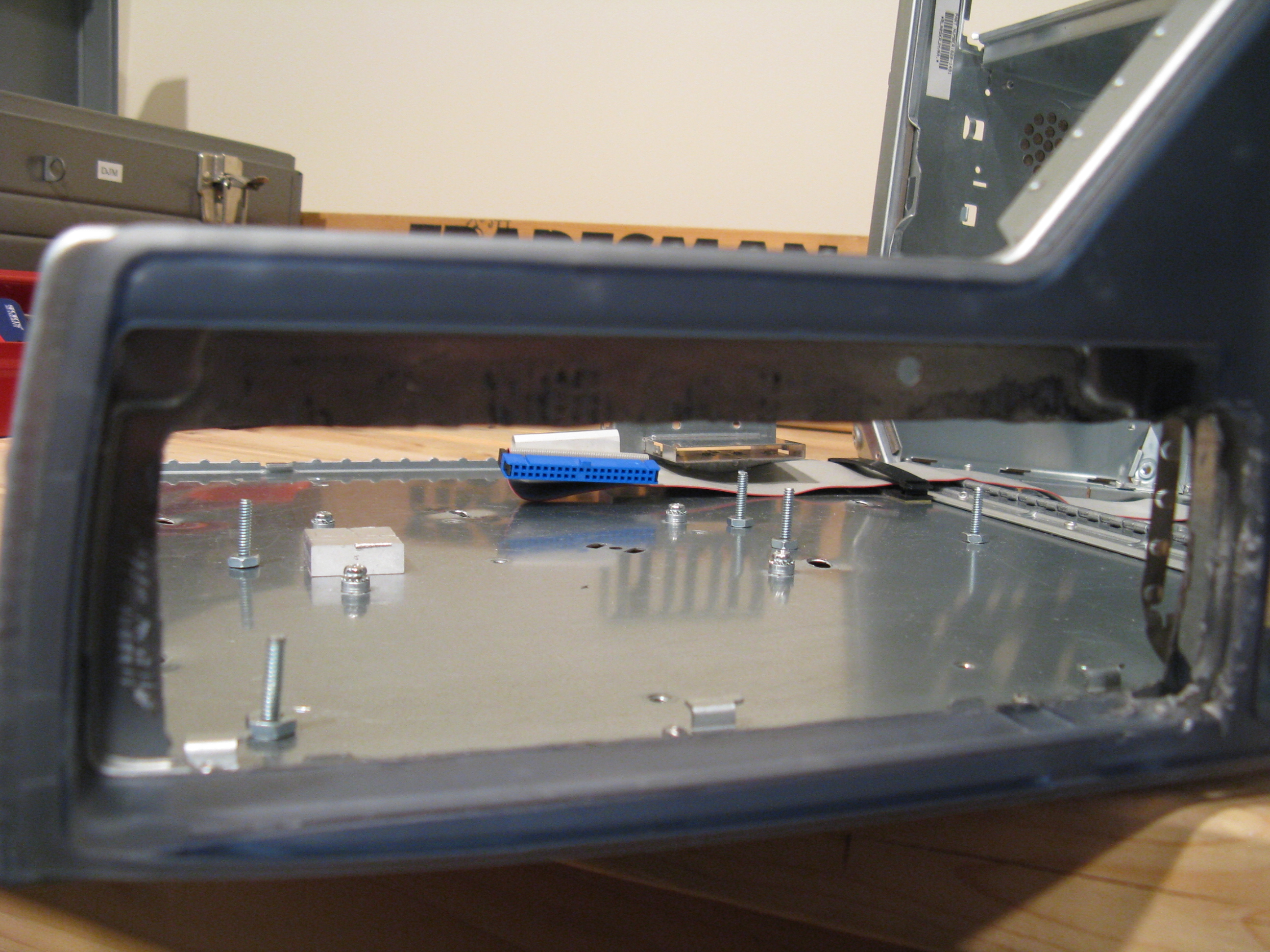
Once you have the holes drilled in the case, you need to make larger holes around them in the plastic sheet that goes under the motherboard and serves as the door latch. Parts of this sheet move when you open the door latch, so those holes need to be oval, not round. The plastic is thick yet a bit brittle. I tried a variety of tools until I had the holes big enough, settling on a 1/2” drill bit, with an xacto knife and round file to clean the edges. Make the holes big enough for the nuts on the motherboard mounting bolts. Any messy work is covered up by the motherboard. Once you have the holes cut in the plastic sheet, clean it off and set it aside.
Fan holes
The stock G4 case doesn’t provide sufficient air flow to cool a modern CPU. The stock Core2 Duo cooler is one of the lower-profile LGA775 coolers I’ve found; it has maybe half an inch of clearance to the power supply, so hot air tends to get trapped around it. The CPU fan is open on the sides, which is probably helpful in this case.
The stock 120mm case fan pulls outside air into the PCI cards area, below the CPU and power supply. There is no place on the back for an exhaust fan. A power supply with a 120mm fan combined with a duct and a suitable low-profile CPU heat sink might sufficiently exhaust the CPU heat, but I didn’t want to get that experimental. Instead, I did what others have done: cut a fan hole in the top of the case. The best place is in the center of the top, between the power supply and the optical drive carrier. I cut a corresponding intake hole in the center of the case bottom, but it’s not necessary.
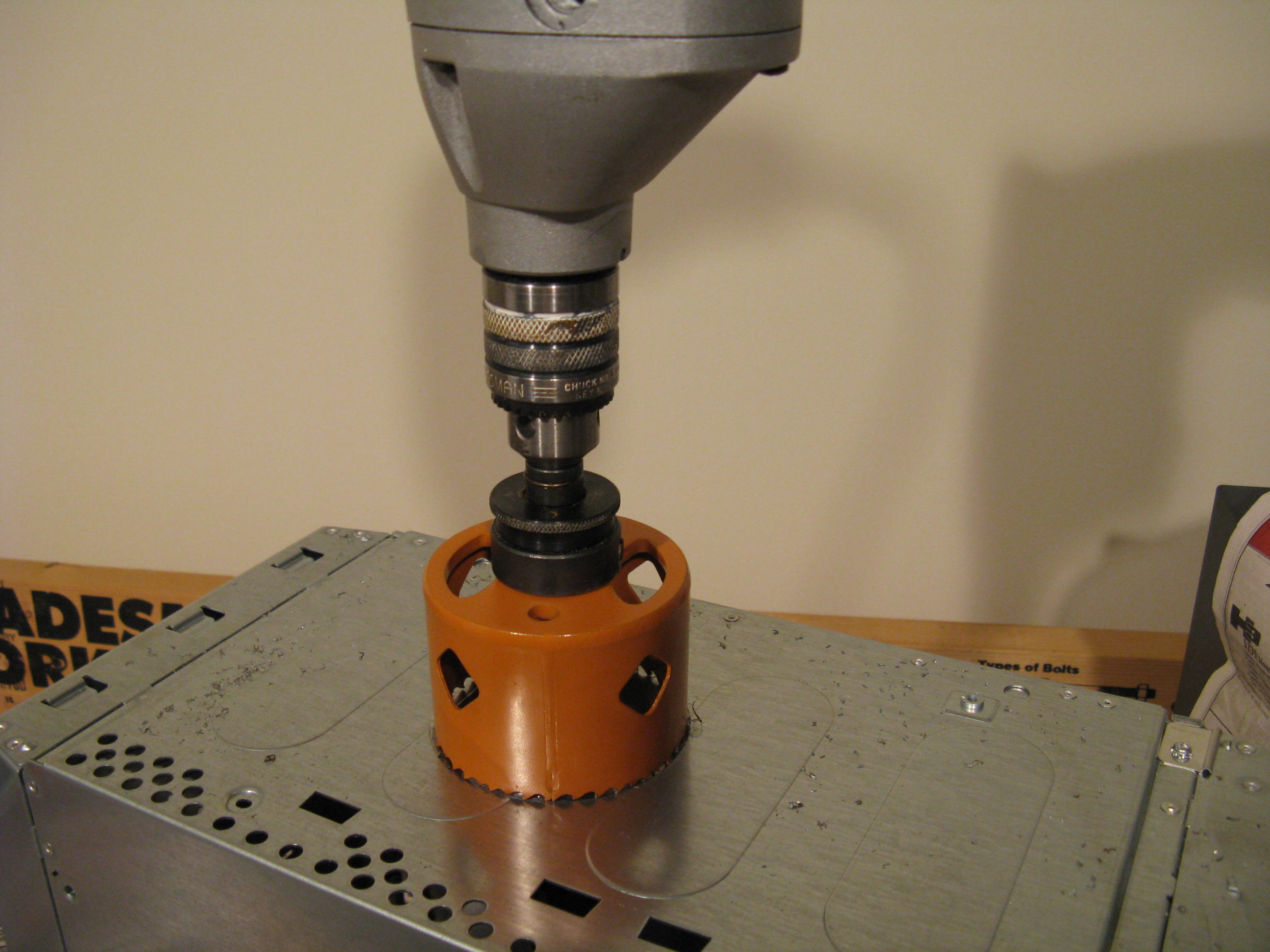
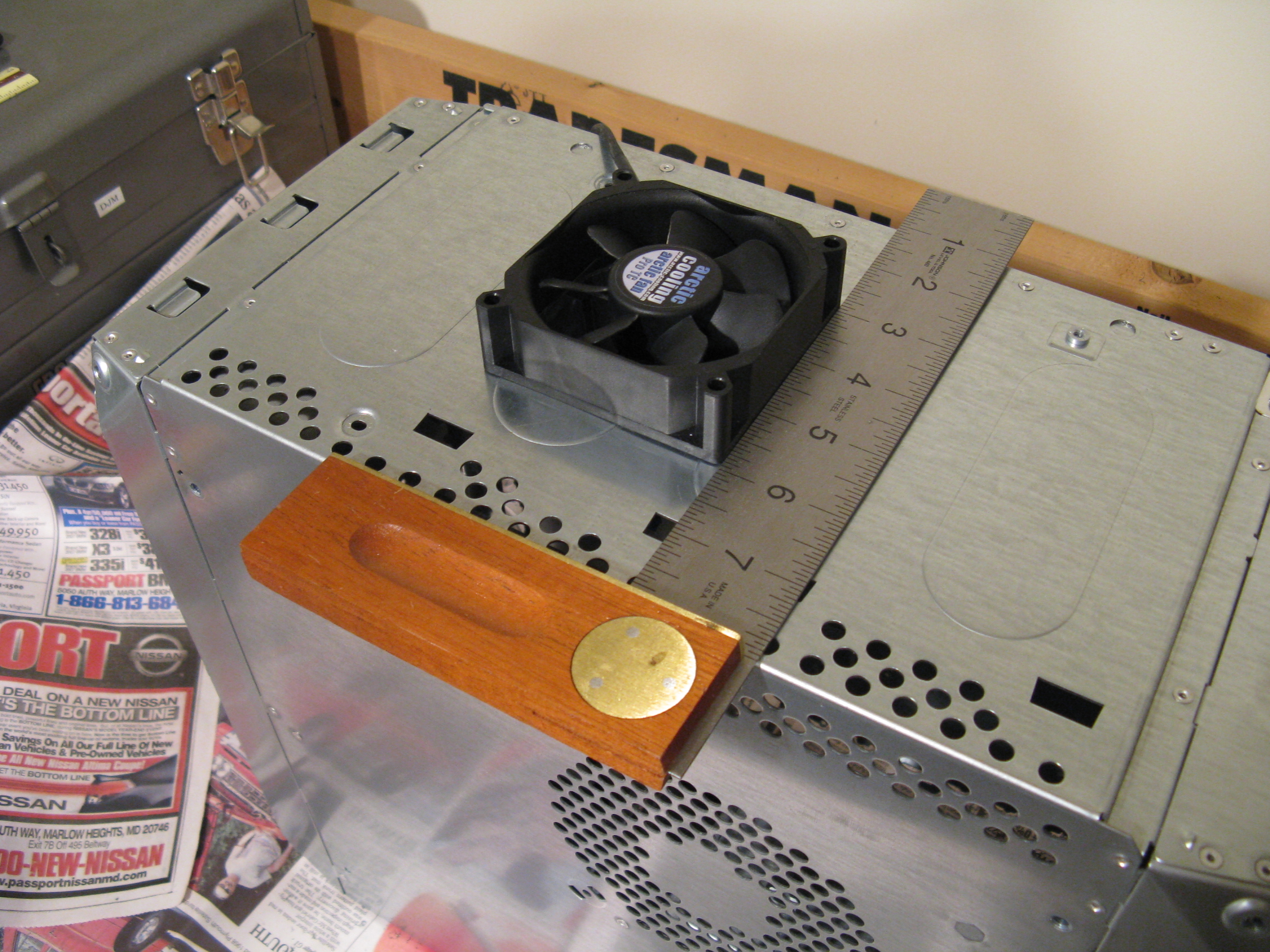
I used a drill with a hole cutting attachment, which made a neat hole that needed only a little filing and sanding to be smooth enough. Then I set the fan dust filter’s frame over the hole and aligned it to the case sides using a carpenter’s square, and drilled the four mounting holes, putting in each screw for alignment after I drilled its hole. It seems best to cut the fan holes with the plastic top in place.
After cutting, remove the plastic top again to clean out the cutting debris. Any imperfections in drilling are covered up by the fan dust filter covers. At first I used an 80mm fan, but it had to run too loudly in order to keep the CPU cool, so I re-cut the hole for a 120mm fan using a jigsaw. The 120mm fan has to be offset to the left side of the case by around half an inch to clear the door latch. The center of the 120mm fan ends up 6 ½” from the front of the case top and 3 ½” from the top of the left side.
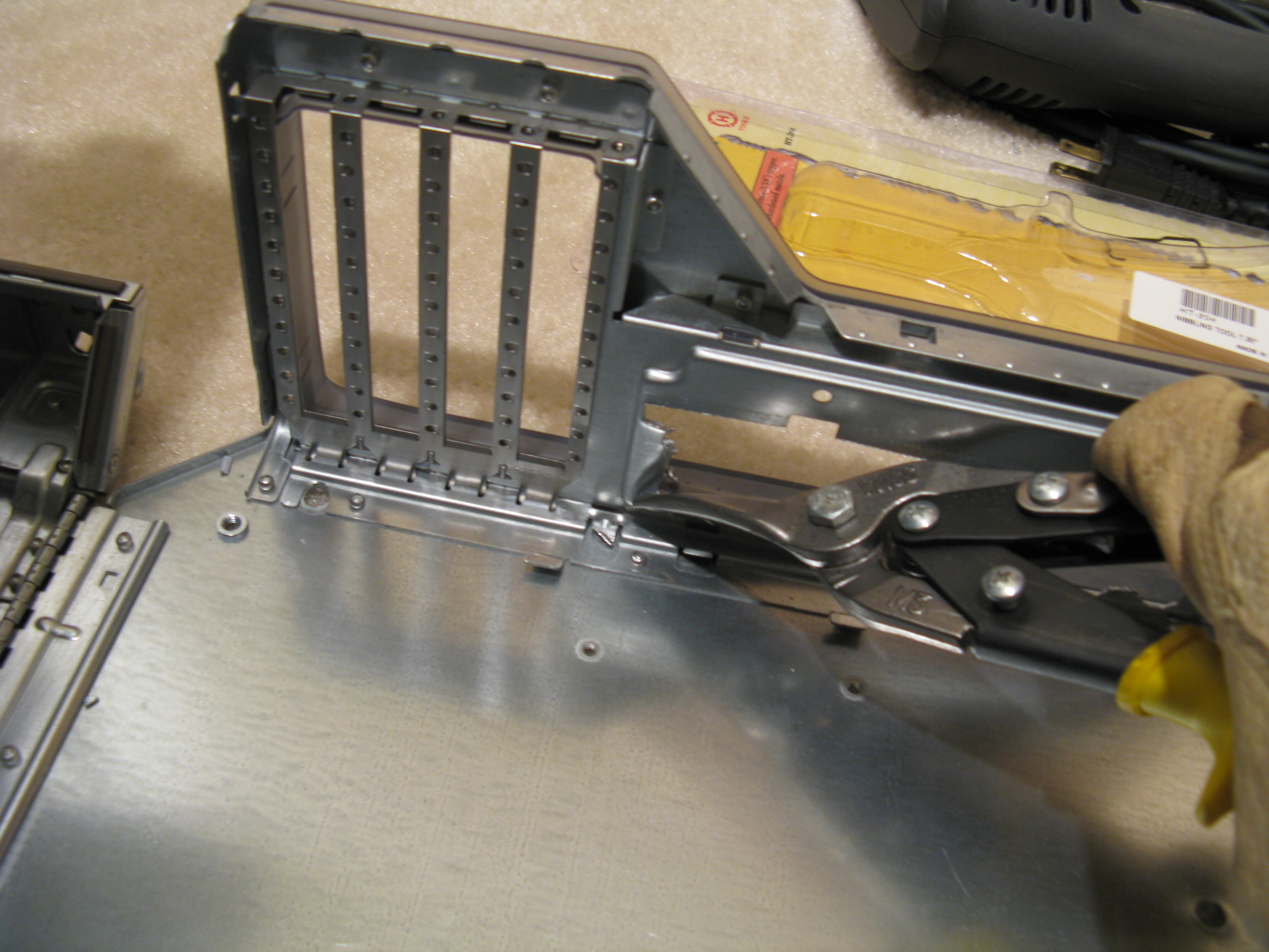
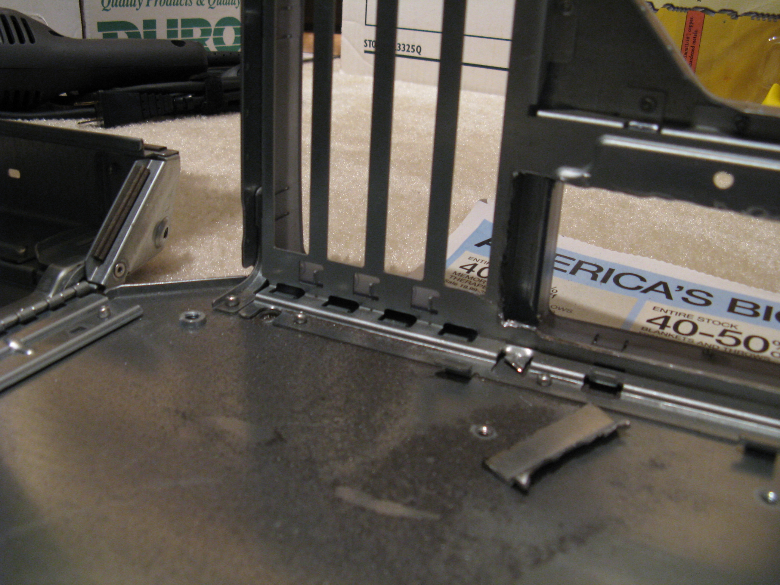
Optical drive cage
Another place I had to compromise on the stock appearance is the optical drive. I couldn’t find a micro ATX LGA775 motherboard narrow enough to clear the optical drive. The RAM and ATX power connector would hit it. Another person used a laptop optical drive in an adapter bracket, but I didn’t want to use a slot-loading drive or cut an awkward slot in the case’s flip-down panel. A tray-loading laptop drive might work, but I didn’t have one to check for the fit or whether it would have problems with the flip-down door.
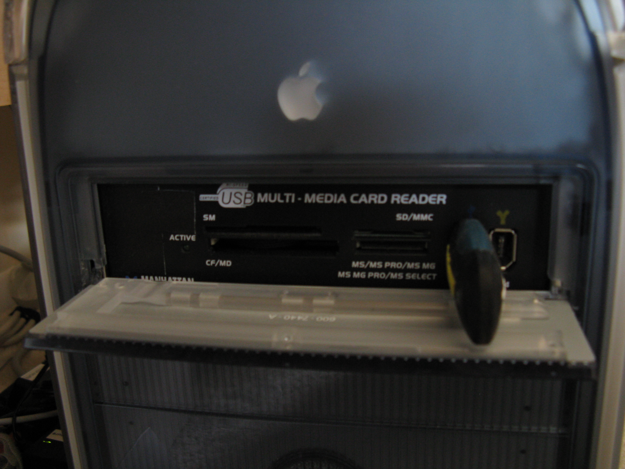
I put a SATA DVD burner in a USB/eSATA enclosure; this motherboard can boot from a USB optical drive. I put a USB/Firewire/flash front ports panel in the computer’s optical drive bay. I had been wanting front ports on the computer anyway, so this was a somewhat elegant solution to two problems at once. The eSATA enclosure is important, as the Apple DVD player only works if you have an ATA or SATA DVD drive installed. I put a SATA to eSATA adapter bracket in the lowest PCI slot.
To clear the motherboard, I had to cut a few inches off of the back of the optical drive cage and notch out the shelf that it sits on. I started using metal snips and nibblers, but switched to a jigsaw.
After all of this cutting, I thoroughly cleaned the case with a vacuum cleaner and a damp rag.
Front panel
To get the power and reset switches and the power light working:
Get three ATX front panel plugs from old PC cases or PC parts suppliers.
Cut off the motherboard end of the Apple ribbon cable and strip the ends.
Use a multitester to verify which wires go to which pins; push in the buttons and check for continuity between pairs of wires (the pinout reportedly changed between generations of PowerMac G4).
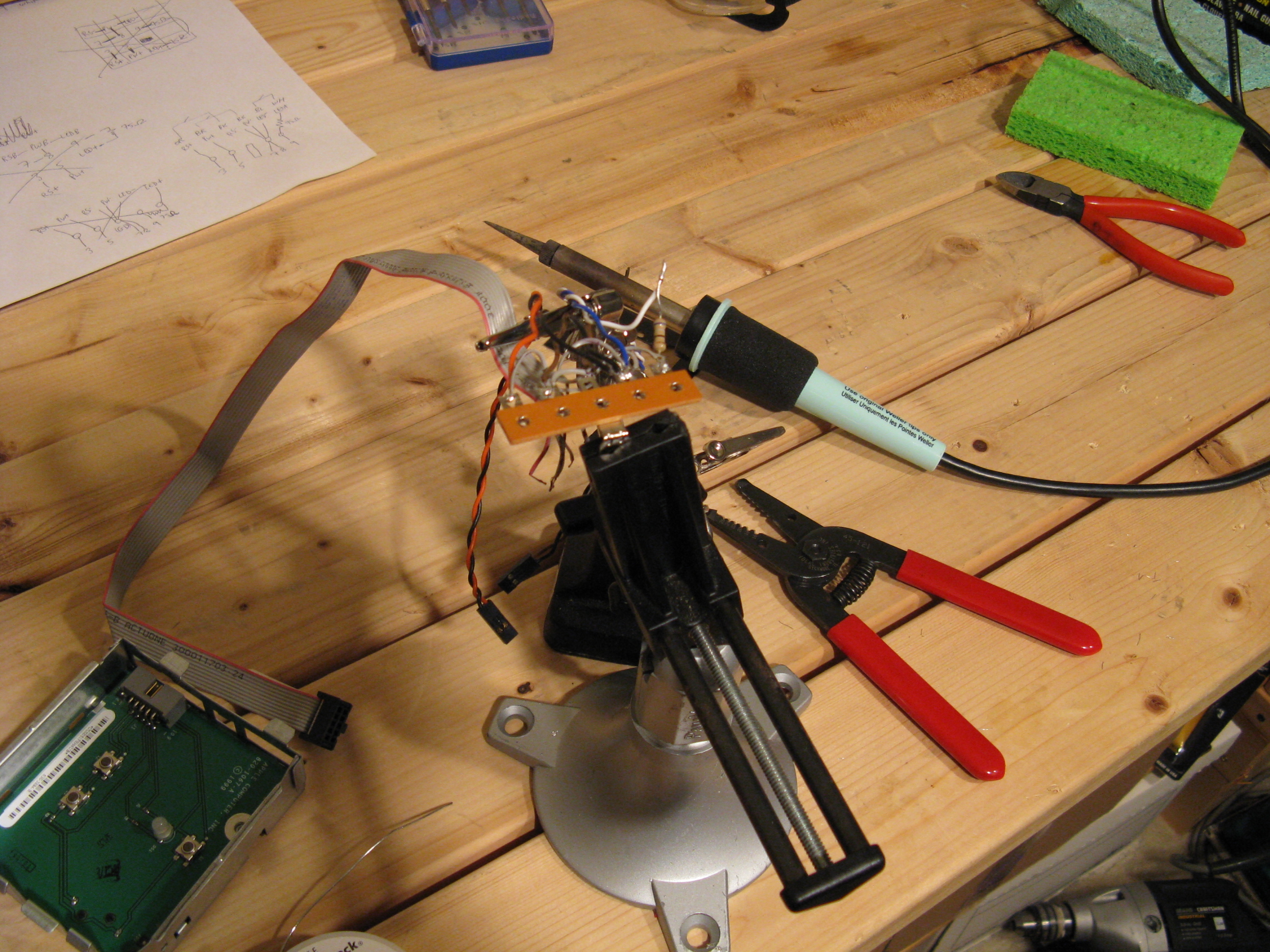
Solder pins on the Apple cable (red pin is 1):
3&8 reset switch
5&8 power switch
9&8 power LED (with 75 Ohm resistor?)
7&8 are ground.
I used a terminal strip as a soldering point, and used double-sided foam tape to stick it on the case door beside the motherboard. I could have bolted it on if I’d finished the wiring before the main reassembly, but the tape works fine.
I left the program switch (pin 1) unconnected, as there’s nothing on the new motherboard to connect it to. The LED is dimmer than with the G4 motherboard; maybe the resistor isn’t needed. It doesn’t bother me enough to fuss with it more.
I haven’t put the speaker back in, as it would just make a beep at boot. It’s not very good for playing music, and I would need to add a switch to disconnect it when using external speakers (which I always use anyway).
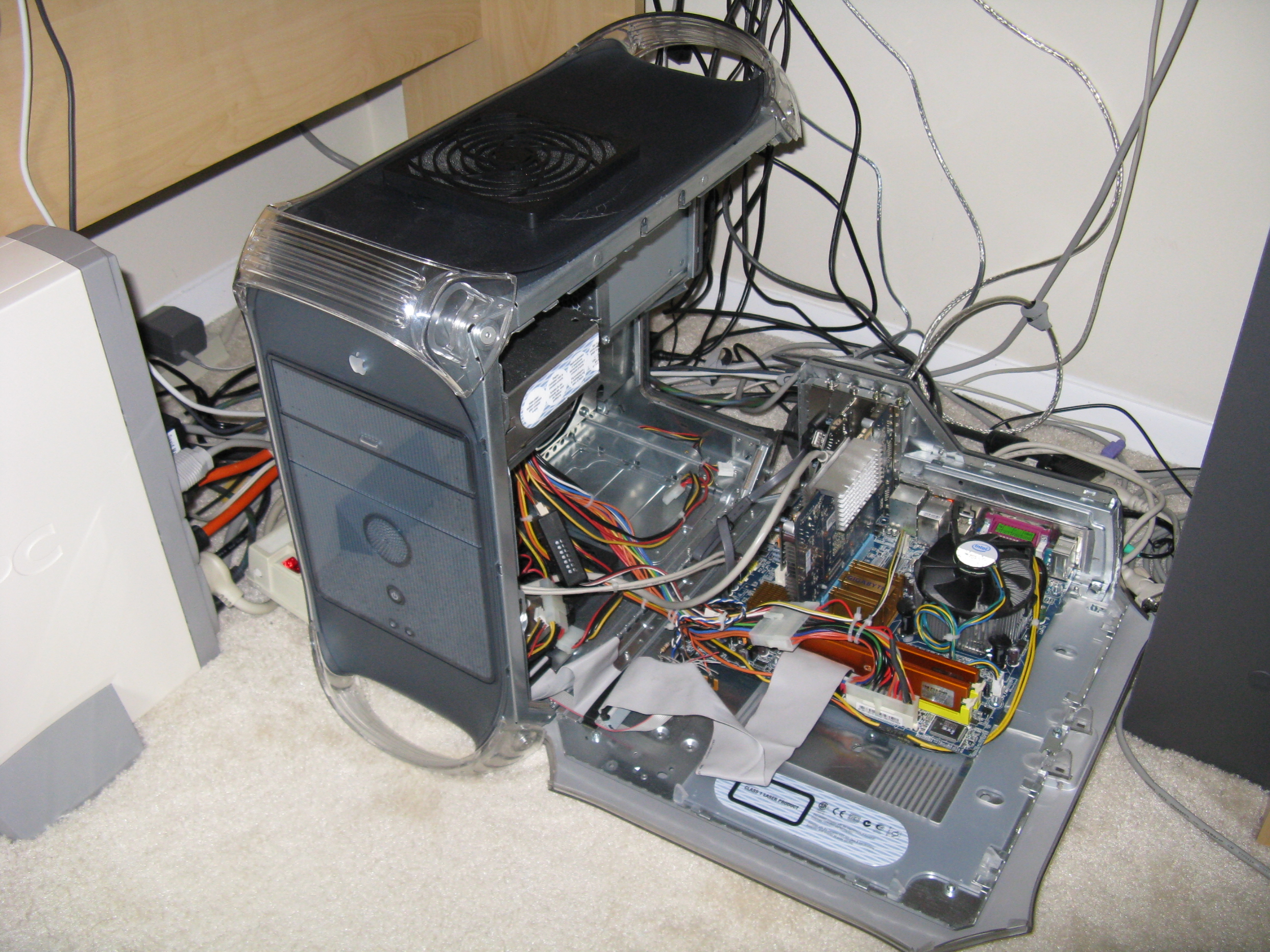
Reassembly
When installing the motherboard, I held on the backplate with cellophane tape because the hole I’d cut wasn’t quite precise enough to hold it securely. Later I added a line of clear silicone caulk inside, around the edges of the backplate, to strengthen the joints. There is still a hole above the plate that I should fill with a piece of metal or plastic, and I’d like to paint the remainder of the original backplate, which had writing on it.
I installed the hard drive on the bracket by the front of the computer, as it is the nearest to the new motherboard’s connectors. A SATA hard drive would have made for neater cable management, but I had an ATA drive that was good enough already, and I wasn’t using the ATA connector for an internal optical drive. I used a shorter ATA cable than it came with, since it didn’t need to reach up to the optical drive bay. Later, after the ATA drive died, I did replace it with a SATA one.
Cooling
At first I didn’t reinstall the stock 120mm case intake fan and bracket, because it didn’t seem to be well ducted and vented and it was rather noisy. Instead, I put a PCI slot cooler in the bottom slot, which has a PCI Express x1 connector I’m not using. However, the slot cooler’s exhaust was cool, so I’m not sure that it accomplished much, and I took it out again. Currently, I have put back the 120mm bracket but with an 800 RPM Scythe fan.
I’m overclocking the Core2 Duo E6600 from the stock 2.4GHz to 3.2GHz stably. It could probably go higher, but I’m concerned about heat in this case. The CPU idles around 48C according to the BIOS, which is acceptable. It idles around 43C with the case door open.
I tried a temperature-controlled 80mm case fan in the top blow hole, but it didn’t spin up to a high enough speed (CPU idled at 60C and CPU fan ran at 2800 RPM). I am currently using a Scythe 120mm fan set to around 1220 RPM. I finally left off the dust filter I had bought because it blocked too much airflow and required the fan to run too loudly. The CPU fan now idles with the case closed barely faster than with the case open (which is around 1400 RPM). The upgraded Intel PowerMac is significantly quieter than when it had the G4 1.4GHz upgrade CPU and stock case fan.
Conclusion
The upgraded PowerMac has the power of a top of the line iMac (as of the time it was built) for around the price of an entry-level Mini. I saved a few hundred dollars by reusing some parts I already had: hard drives, power supply, and Firewire and USB cards (and keyboard, video display and mouse).
It’s a significant project to take on; the first one took me around 3 weeks of evenings and weekends. A second one took less time because I knew what to do and had all the tools already. It’s satisfying to prove it’s possible and then be able to use it. This 1999 PowerMac lives on, with 16 times the CPU clock speed it shipped with!
Similar projects
http://www.s155158671.websitehome.co.uk/winmacpcinaapple.html
http://www.slcentral.com/articles/01/8/g4pc/
http://forum.insanelymac.com/index.php?showtopic=59926
http://handmademac.googlepages.com/home
http://web.mac.com/andywright153/iWeb/iHack%21/The%20iHack%21%20Project.html
http://homepage.mac.com/cycline3/pc-to-mac/index.html
http://www.barovelli.com/projects/comp/badapple/index.html
http://www.xlr8yourmac.com/systems/ATX_G4_AGP_conversion/G4_AGP_to_ATX_case.htm
Parts list
• PowerMac G4 case (the oldest models are the easiest to adapt for ATX)
• ATX power supply with 80mm fan (not 120mm unless you use a CPU cooler that works fanless or sucking instead of blowing and can survive the CPU heat)
• Micro ATX LGA775 motherboard (e.g., Gigabyte GA-G41M-ES2L)
• Intel Core2 Duo or Quad desktop CPU (e.g., E6600, E8400, Q9550S)
• Low-profile CPU cooler (65mm or shorter, e.g., Intel stock or perhaps Scythe SCSK-1000 “SHURIKEN”)
• PC2-6400 (DDR2 800) RAM (e.g., Geil, Crucial)
• PCI-E video card (e.g., ASUS EN7300GT, ASUS EN9400GT)
• Firewire PCI or PCI-E card with an internal port, if not on motherboard
• USB2 PCI card (optional)
• 3.5” front ports panel (e.g., SilverStone FP32) with 3.5” to 5.25” adapter bracket, or 5.25″ front ports panel (e.g., Manhattan 702775)
• Hard drive, SATA or ATA
• SATA or ATA data cable
• SATA DVD-R drive in USB/eSATA enclosure
• 120mm medium-speed exhaust fan (e.g., Scythe S-FLEX SFF21F)
• 120mm low-speed intake fan (e.g., Scythe S-FLEX SFF21D)
• Fan speed control for exhaust fan (e.g., Zalman Fanmate 2)
• 120mm fan dust filter
• #6-32 machine bolts and nuts: 6 x ¾” bolts for motherboard (2 nuts per bolt) and 4 x 1 ½” bolts for top fan (1 nut per bolt)
• ATX motherboard power (24 pin) extension, 6”-12”
• ATX CPU power (4 pin) extension, 12”
• Molex 4-pin to 3-pin fan header adapter, or fan header extension
• Firewire male header to 6 pin adapter cable (if using PCI Firewire card; e.g., Performance PC’s 1394-2MHEADER)
• Terminal strip for front panel (solder type, 5 lug points of which we use 4)
• ATX plugs for motherboard front panel connections (3, for power/reset/LED)
• 75 Ohm resistor for LED (might not be needed)
• ATX speaker plug (optional)
• Zip ties
• Anti-static bag to cut up (for AGP Graphics model)
• Solder
• Fine grit sandpaper (e.g., 100 grit)
• Cellophane tape (e.g., Scotch)
• Rags
• Newspaper
• Goo remover
Tools
• 3/32” Allen (hex) wrench
• metal snips (e.g., Wiss M3)
• Nibbling cutter (e.g., Hanlong Tools HT-204)
• Phillips and slot head screw drivers
• Dremel tool with #420 heavy duty cut-off wheels and #9903 Tungsten Carbide Cutter
• Round file
• Pliers
• Needle-nose pliers
• Jigsaw with metal cutting blade
• Drill with hole saw attachment (4.5” for 120mm, optional)
• Drill bit for fan and motherboard screws, 9/64”
• Clamps
• Carpenter’s square
• Tape measure
• Pencil
• Spray-mount adhesive (e.g., 3M Super 77) (for AGP Graphics model)
• Epoxy or silicone
• Wire cutters
• Utility knife
• Heat gun
• Soldering iron
• Protective goggles

You must be logged in to post a comment.